- 您现在的位置:买卖IC网 > Sheet目录3753 > ATMEGA169P-16MCHR (Atmel)MCU AVR 16KB FLASH 16MHZ 64-VQFN
PIC16F946
DS41265A-page 210
Preliminary
2005 Microchip Technology Inc.
16.8
Code Protection
If
the
code
protection
bit(s)
have
not
been
programmed, the on-chip program memory can be
read out using ICSP for verification purposes.
16.9
ID Locations
Four memory locations (2000h-2003h) are designated
as ID locations where the user can store checksum or
other code identification numbers. These locations are
not accessible during normal execution, but are
readable and writable during Program/Verify mode.
Only the Least Significant 7 bits of the ID locations are
used.
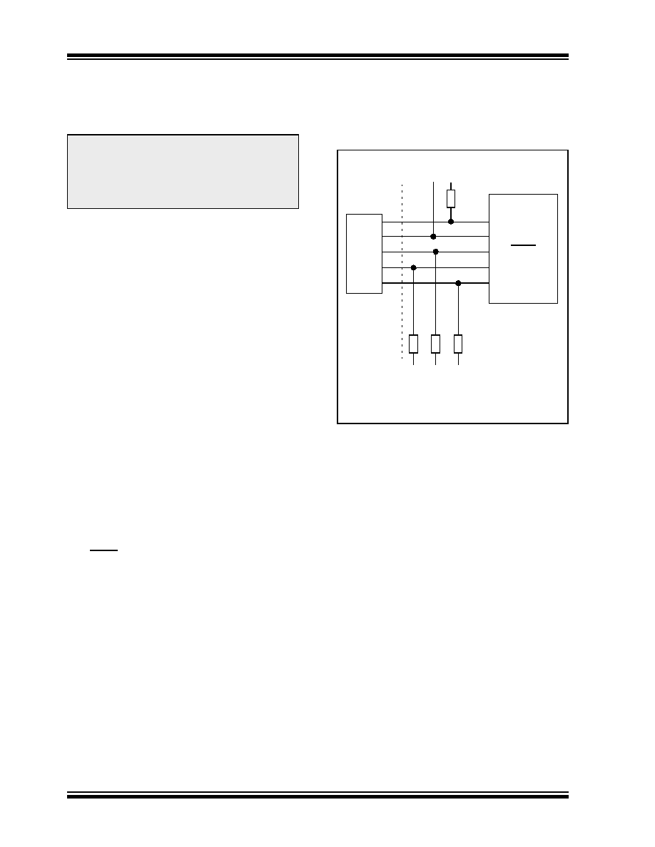
16.10 In-Circuit Serial Programming
The PIC16F946 microcontrollers can be serially
programmed while in the end application circuit. This is
simply done with two lines for clock and data and three
other lines for:
power
ground
programming voltage
This allows customers to manufacture boards with
unprogrammed devices and then program the micro-
controller just before shipping the product. This also
allows the most recent firmware or a custom firmware
to be programmed.
The device is placed into a Program/Verify mode by
holding
the
RB7/ICSPDAT/ICDDAT/SEG13
and
RB6/ICSPCLK/ICDCK/SEG14 pins low, while raising
the
MCLR
(VPP)
pin
from
VIL
to
VIHH.
See
“PIC16F91X/946 Memory Programming Specification”
(DS41244) for more information. RB7/ICSPDAT/ICD-
DAT/SEG13 becomes the programming data and
RB6/ICSPCLK/ICDCK/SEG14 becomes the program-
ming clock. Both RB7/ICSPDAT/ICDDAT/SEG13 and
RB6/ICSPCLK/ICDCK/SEG14 are Schmitt Trigger
inputs in this mode.
After Reset, to place the device into Program/Verify
mode, the Program Counter (PC) is at location 00h. A
6-bit command is then supplied to the device.
Depending on the command, 14 bits of program data
are then supplied to or from the device, depending on
whether the command was a load or a read. For
complete details of serial programming, please refer to
the
“PIC16F91X/946
Memory
Programming
Specification” (DS41244).
A typical In-Circuit Serial Programming connection is
shown in Figure 16-11.
FIGURE 16-11:
TYPICAL IN-CIRCUIT
SERIAL PROGRAMMING
CONNECTION
Note:
The entire data EEPROM and Flash
program memory will be erased when the
code protection is turned off. See the
“PIC16F91X/946 Memory Programming
Specification” (DS41244) for more infor-
mation.
External
Connector
Signals
To Normal
Connections
To Normal
Connections
PIC16F946
VDD
VSS
RE3/MCLR/VPP
RB6/ICSPCLK/
RB7/ICSPDATA/
+5V
0V
VPP
CLK
Data I/O
*
* Isolation devices (as required)
ICDCK/SEG14
ICDDAT/SEG13
发布紧急采购,3分钟左右您将得到回复。
相关PDF资料
2-1546217-0
TERM BLK RCPT 20POS SIDE 5.08MM
1-1546217-9
TERM BLK RCPT 19POS SIDE 5.08MM
1-1546217-8
TERM BLK RCPT 18POS SIDE 5.08MM
1-1546217-7
TERM BLK RCPT 17POS SIDE 5.08MM
1-1546217-6
TERM BLK RCPT 16POS SIDE 5.08MM
1-1546217-5
TERM BLK RCPT 15POS SIDE 5.08MM
1-1546217-4
TERM BLK RCPT 14POS SIDE 5.08MM
1-1546217-3
TERM BLK RCPT 13POS SIDE 5.08MM
相关代理商/技术参数
ATMEGA169P-16MCU
功能描述:8位微控制器 -MCU AVR 16KB, 512B EE 16MHz 1KB SRAM, 5V
RoHS:否 制造商:Silicon Labs 核心:8051 处理器系列:C8051F39x 数据总线宽度:8 bit 最大时钟频率:50 MHz 程序存储器大小:16 KB 数据 RAM 大小:1 KB 片上 ADC:Yes 工作电源电压:1.8 V to 3.6 V 工作温度范围:- 40 C to + 105 C 封装 / 箱体:QFN-20 安装风格:SMD/SMT
ATMEGA169P-16MU
功能描述:8位微控制器 -MCU AVR 16K FLASH 512B EE 1K SRAM LCD ADC RoHS:否 制造商:Silicon Labs 核心:8051 处理器系列:C8051F39x 数据总线宽度:8 bit 最大时钟频率:50 MHz 程序存储器大小:16 KB 数据 RAM 大小:1 KB 片上 ADC:Yes 工作电源电压:1.8 V to 3.6 V 工作温度范围:- 40 C to + 105 C 封装 / 箱体:QFN-20 安装风格:SMD/SMT
ATMEGA169P-16MU SL383
制造商:Atmel Corporation 功能描述:MCU 8BIT ATMEGA RISC 16KB FLASH 3.3V/5V 64PIN MLF - Tape and Reel
ATMEGA169P-16MUR
功能描述:8位微控制器 -MCU AVR LCD 16KB FLSH EE 512B 1KB SRAM-16MHZ RoHS:否 制造商:Silicon Labs 核心:8051 处理器系列:C8051F39x 数据总线宽度:8 bit 最大时钟频率:50 MHz 程序存储器大小:16 KB 数据 RAM 大小:1 KB 片上 ADC:Yes 工作电源电压:1.8 V to 3.6 V 工作温度范围:- 40 C to + 105 C 封装 / 箱体:QFN-20 安装风格:SMD/SMT
ATMEGA169P-8AU
制造商:ATMEL 制造商全称:ATMEL Corporation 功能描述:Microcontroller with 16K Bytes In-System Programmable Flash
ATMEGA169P-8MU
制造商:ATMEL 制造商全称:ATMEL Corporation 功能描述:Microcontroller with 16K Bytes In-System Programmable Flash
ATMEGA169PA
制造商:ATMEL 制造商全称:ATMEL Corporation 功能描述:8-bit Microcontroller with 16K Bytes In-System Programmable Flash
ATMEGA169PA_1
制造商:ATMEL 制造商全称:ATMEL Corporation 功能描述:High Endurance Non-volatile Memory segments